ASIO Audio Test signal generator specifications
*ASIO is a trademark of Steinberg Media Technologies GmbH
The goal was to produce a generator of audio frequency sine wave signals of the highest possible quality that may be used as a frequency standard for testing all components in the path of the signal. A very thorough specification follows, with the aim to increase the usefulness of the signal generator for sound engineers.
The sine wave generator
In the quest to create "the perfect wave", the floating point calculations that produce the sine wave employ 80 bits of internal precision. A continuous sine wave may be generated at frequencies up to half the sample rate (Nyquist limit). They begin with a fade up and end with a fade down, both equal to some number of whole cycles. (In the end, the frequency can only be as accurate as the clock used by the sound card, but its accuracy will allow one to determine the accuracy of the clock.)
The tone burst is a perfectly symmetrical series of whole waves so as to end up with a negligible DC component. Whatever DC remains is removed, so that for any given frequency of 10 seconds duration or less, the DC level is guaranteed to be 0. The actual DC level before correction is pre-calculated on a sample by sample basis. DC correction is not applied to signals of a duration greater than 10 seconds.
Each sine wave signal generated begins and ends with a smooth linear taper of exact multiples of the period to eliminate speaker pops and clicks (see image above). The taper length depends on the duration of the signal requested, with the maximum duration set to approximately 0.01 seconds. The minimum taper length is equal to the period of the requested frequency.
Signal duration is equal to exact multiples of the period at the requested frequency, such that they add up to at least the duration requested in seconds.
Minimum signal duration is limited to the nearest exact multiple of the period equal to or greater than 0.01 seconds, or the time it takes to play two whole waves at the requested frequency - whichever is greater.
To avoid saturation while allowing room for DC correction - should it be required, the maximum signal value is limited in absolute terms to max_amplitude - 2, as follows...
Absolute value of maximum 32 bit amplitude = 0x7FFFFFFD hex
Absolute value of maximum 24 bit amplitude = 0x007FFFFD hex
Absolute value of maximum 16 bit amplitude = 0x00007FFD hex
Maximum 32 bit dBs ~= 186.6
Maximum 24 bit dBs ~= 138.5
Maximum 16 bit dBs ~= 90.3
The minimum attenuation is 0 dB.
Maximum attenuation permitted is 90 dB.
If attenuation is applied, the signal level is calculated based on:
0 dBs defined as 20 x log10(0x7FFFFFFF) for 32 bit sound card
0 dBs defined as 20 x log10(0x007FFFFF) for 24 bit sound cards
0 dbs defined as 20 x log10(0x00007FFF) for 16 bit sound cards
Attenuation is also calculated with the highest precision possible.
The sweep wave generator
The sweep generator employs a swept sine wave function and does not include DC correction. You may choose between a linear or a logarithmic sweep. It can sweep up or down. The samples are generated in real time - as in the case with the sine wave generator - directly into the sound card's buffers with no pre-buffering. The minimum frequency is 10 Hz and the maximum frequency is 22050 Hz. Attenuation values allowed are the same as for the tone burst generator. The minimum sweep duration is 0.01 seconds and the maximum is 60 seconds. Duration is rounded up to the nearest multiple of sound buffer's sample size. A linear taper is applied to the end of the signal, of a duration equal to the sound card's buffer sample size. During taper down, the frequency is held at the ending frequency requested.
The white noise generator
The latest version (2.20) has a white Gaussian noise generator. The pseudo-random number generator employs the "Mother-Of-All" generator invented by George Marsaglia and provides an excellent even distribution. The code for this can be found at https://www.agner.org/random/. The overlaid Gaussian window is a codification of the Box-Muller transform in its basic form to provide a zero-centered normal distribution of the samples. The output was thoroughly tested to ensure uniform distribution with a Gaussian curve.
The pink noise generator
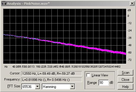
The pink noise generator employs an algorithm by Andrew Simper of Vellocet, a C++ implementation derived from the code provided by the following people mainly from the music-dsp mailing list: Allan Herriman, James McCartney, Phil Burk and Paul Kellet and the web page by Robin Whittle: https://www.firstpr.com.au/dsp/pink-noise/
Warning - pink noise contains frequencies below the range of hearing that may damage your speakers at very high levels. Turn down the bass if you want to pump up the sound, or watch your speaker cones for excessive movement.
From Wikipedia: "Pink noise, also known as 1/f noise, is a signal or process with a frequency spectrum such that the power spectral density is proportional to the reciprocal of the frequency. There is equal energy in all octaves (or similar log bundles). In terms of power at a constant bandwidth, 1/f noise falls off at 3 dB per octave. At high enough frequencies 1/f noise is never dominant. (White noise is equal energy per hertz.) 1/f noise occurs in many physical, biological and economic systems." Below are images showing spectral views of the signals produced by the Audio Test Signal Generator
Note to programmers
The basic algorithm for generating a sine wave couldn't be simpler: sample = amplitude * sin(phaseAngle), but I managed to make it so complicated that it took considerable time to develop this. The difficulties sprang from the desire to generate signals in real time without pre-buffering, and ensuring that the tapers begin and end exactly at the zero crossing. It is not always easy to predict where to find the zero crossing with a broad range of frequencies and durations. With a real time signal, we need to know in advance at what sample number in which buffer load of data it is to be found. DC correction in real time also added to the challenges.